| Item | Specification | |
|---|---|---|
| Number of axes | 1 | |
| Enclosure | Panel mount | |
| Protective case | IP20 (built into IP54 panel) | |
| Grounding | 200 V class D grounding, 100 Ω or less | |
| Vibration resistance | 10 to 60 Hz at an acceleration of 5.88 m/s2 or less
(Not to be run continuously at the resonant frequency) |
|
| Air flow clearance | Refer to installation section | |
| Mounting screws tightening torque | 1.2 Nm | |
| Cooling | Natural convection and built-in fan | |
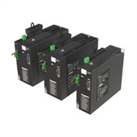
| Weight | CK3A-G305L | 1.81 kg |
| CK3A-G310L | 2.67 kg | |
| CK3A-G320L | 2.77 kg | |
| Dimensions | CK3A-G305L | 212.5 x 65.0 x 180.0 mm |
| CK3A-G310L | 238.0 x 90.0 x 180.0 mm | |
| CK3A-G320L | 238.0 x 90.0 x 180.0 mm | |
| Regulations
and Standards |
Conformance to
EU Directives |
EMC Directive: EN61800-3 second environment
Low Voltage Directive: EN61800-5-1 C2 category Functional Safety: EN61800-5-2 SIL3 (STO) |
| Conformance to
UL Directives |
UL Standards: UL 61800-5-1
CSA Standards: CSA C22.2 No. 274 |
|
| Conformance to
UKCA Standards |
UKCA: 2016 No. 1091
UKCA: 2016 No. 1101 EMC Directive: 2016 No. 1091 Low Voltage Directive: 2016 No. 1101 Functional Safety: 2008 No. 1597 |
|
| Conformance to
KC Standards |
Immunity Standard for Industrial Environments: KS C 9610-6-2
Emission Standard for Industrial Environments: KS C 9610-6-4 |
|