| 容量 | 240W | 480W | 960W | ||
|---|---|---|---|---|---|
| 輸出電壓(DC) | 24V | 24V | 24V | ||
| 效率*1 | 三相 AC400V輸入時 | 93% typ. | 94% typ. | 95% typ. | |
| 二相 AC400V輸入時 | 93% typ. | 94% typ. | 95% typ. | ||
| 輸入條件 | 輸入電壓容許範圍 *2 | 三相、二相 AC320 ~ 576V
DC450 ~ 810V |
|||
| 頻率 *2 | 50/60 Hz (47 to 63 Hz) | ||||
| 輸入電流 *1 | 三相 AC400V輸入時 | 0.41 A typ. | 0.79 A typ. | 1.6 A typ. | |
| 二相 AC400V輸入時 | 0.75 A typ. | 1.5 A typ. | 3.0 A typ. | ||
| 功率 *1 | 三相 AC400V輸入時 | 0.9以上 | |||
| 漏電流 *3 | 三相 AC400V輸入時 | 3.5 mA 以下 | |||
| 突波電流 *4
(25℃、冷開機) |
三相 AC400V輸入時 | 1.9 A typ. | 3.3 A typ. | 10.6 A typ. | |
| 輸出特性 | 額定輸出電流 | 10 A | 20 A | 40 A | |
| 峰值電流 | 15 A | 30 A | 60 A | ||
| 電壓可變範圍 *5 | 24 ~ 29.5V (V.ADJ時) | 24 ~ 28V (V.ADJ時) | |||
| 漣波雜訊電壓 *6 | 三相
AC380 ~ 480V輸入時 |
100mVp-p以下
頻率帶20MHz時 |
80mVp-p以下
頻率帶20MHz時 |
50mVp-p以下
頻率帶20MHz時 |
|
| 靜態輸入變化影響 *7 | 0.5% 以下 | ||||
| 靜態負載變化影響 *8 | 1.5%以下 | ||||
| 溫度變化 | 三相
AC380 ~ 480V輸入時 |
0.05%/°C 以下 | |||
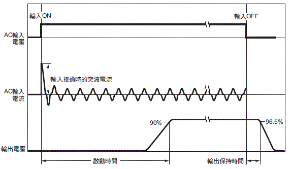
| 啟動時間 *9 | 三相 AC400V輸入時 | 1,000 ms 以下 | |||
| 輸出保持時間 *9 | 三相 AC400V輸入時 | 30 ms typ. | 25 ms typ. | 20 ms typ. | |
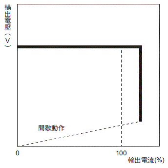
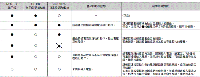
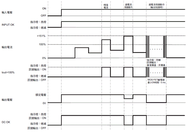
| 附加功能 | 過電流保護 | 有、自動復歸、間歇性動作型
請參閱第22頁的「●過電流保護」。 |
|||
| 過電壓保護 | 有、額定輸出電壓的130%以上、遮斷(斷電復歸)
請參閱第22頁的「●過電壓保護」。 |
||||
| 串聯操作 | 可(最多2台,需外部二極體) | ||||
| 並聯操作 | 可(最多2台) 詳情請參閱第34頁的「●並聯操作」。 | ||||
| INPUT OK指示燈 | 有(LED,顏色:綠) | ||||
| DC OK指示燈 | 有(LED,顏色:綠) | ||||
| Iout>100%指示燈 | 有(LED,顏色:黃) | ||||
| DC OK訊號輸出 | 有(MOS FET繼電器輸出 DC30V max、50mA max) | ||||
| Iout>100%訊號輸出 | 有(MOS FET繼電器輸出 DC30V max、50mA max) | ||||
| 絕緣耐壓 | 耐電壓 | AC3.0kV 1min (所有輸入端子)與(所有輸出端子、訊號輸出端子)之間 截斷電流20mA | |||
AC2.5kV 1min (所有輸入端子)與( )之間、截斷電流20mA )之間、截斷電流20mA |
|||||
AC1.0kV 1min (所有輸出端子、訊號輸出端子)與( )之間 截斷電流30mA )之間 截斷電流30mA |
|||||
| AC0.5kV 1min (所有輸出端子)與(所有訊號輸出端子)之間 截斷電流10mA | |||||
| 絕緣阻抗 | 100MΩ以上、DC500V (所有輸出端子、訊號輸出端子)與(所有輸入端子、 )之間 )之間 |
||||
| 環境 | 使用環境溫度*10 | -40 ~ +70℃ (會因溫度造成降額) (不可結露結冰) | |||
| 保存溫度 | -40 ~ +85℃ (不可結露結冰) | ||||
| 使用環境濕度 | 95%RH以下(保存濕度95%RH以下) | ||||
| 抗震性 *11 | 10 ~ 55Hz、最大5G單側振幅0.42mm 3方向 各2h | ||||
| 耐衝擊 *11 | 294m/s2 6方向 各3次 | ||||
| 信賴性 | MTBF *12 | 13.5萬小時以上 | 13.5萬小時以上 | 6萬小時以上 | |
| 期待壽命 *13 | 10年以上 | ||||
| 構造 | 重量 | 890 g 以下 | 1,200g以下 | 1,800 g 以下 | |
| 冷卻風扇 | 無 | ||||
| 保護構造 | 依據IP20 by EN/IEC 60529 | ||||
